Electric engine cooling and lubrication (Part 2: Centrifugal oil injection)
This article follows a previous article “Electric engine cooling and lubrication (Part 1: Oil jet under aerodynamic load)” (https://lnkd.in/dwhaUpi). After focusing on oil injection through fixed nozzle to cool and lubricate e-motors, we will focus herein on another technology: oil injection through engine shaft.
As for oil nozzle injection, centrifugal injection sprinkles oil directly over hot internal parts such as rotor and stator. Oil nonconductivity makes possible to sprinkle electric wires and coils without short-circuit risk. This technology takes full advantage of the centrifugal effect to spread oil in the shaft. Oil is sprayed in several rotating jets, this centrifugal technology provides often a better ability than fixed nozzle technology to wet all e-motor internal surfaces.
However, centrifugal injection cooling is more challenging to design than still nozzle cooling. Indeed, it is difficult to target the hot parts and to predict whether they are well wetted. In addition, the flow through the shaft is complex since it depends on rotating speed, viscosity, and oil supply. Whereas oil supply is straightforward in case of still shaft with rotating frame (in-wheel embedded e-motors), the design of rotating shaft oil channel supply adds an extra complexity to solve. The high rotor rotating speed (more than 14 000 rpm) avoids the use of conventional gasket.

As shown on the above blueprint, the design solution is based on a conic nozzle flowing in the rotor shaft hole, keeping a little gap between nozzle and shaft. The sealing is not guaranteed even if the gap is little and the oil relatively viscous. Therefore, the rotor undergoes a so-called backflow coupled with the shaft oil channel pressure.
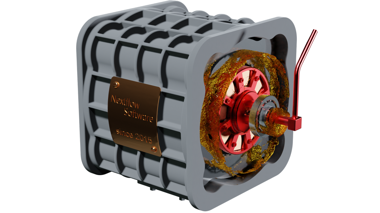
The resulting heat-flux extracted from internal parts depends on a lot of parameters which makes Computational Fluid Dynamics (CFD) the only suitable tool to address such a problem. A Lagrangian approach, especially the Smoothed Particle Hydrodynamics (SPH) method is one of the best CFD approaches to compute such flow due its intrinsic ability to handle complex free surfaces. In the present study, we have slightly changed our in-house e-motor geometry earlier presented with fixed oil injection cooling. It is designed in similar manner, still representative of an automotive e-motor.

The oil is supplied to the rotor shaft thanks to an inlet located in the conic nozzle system. Bodies are defined isothermal. The rotor and stator are warmed by Joule effect at approximately 363K (depicted in orange on the left figure). The frame is kept to atmospheric temperature at 293K (depicted in blue on the left figure). Like in the previous article, the rotor rotating speed is set at 14 000 rpm and the global oil flow is approximatively 0.2 kg/s.
The heat exchange between hot rotor/stator and cold frame using oil is displayed on the graph below. The rotor heat-flux is higher than stator heat-flux due to the intense exchange in the shaft channel. The heat-flux resulting from the body sprinkling is less steady than full oil contact and needs more simulation time to be representative. It points out the intrinsic complexity to obtain temporally converged thermal results for such flow. Therefore, the flow dynamics is strong, and the flow characteristic time is far smaller than the thermal characteristic time of the parts. Note that a Conjugated Heat Transfer (CHT) strategy which corresponds to a coupling between CFD solver and solid heat conduction solver will be addressed in a future article.

Plane flow sensors are attached to rotating parts in the simulation, to study flow distribution of rotor shaft radial holes. The shaft has three radial holes at each end which point toward rotor coil sides. The plot below lays out the front and rear average flows through radial holes. One can notice that the hole diameters are not designed to obtain the same flowrate at 14000 rpm despite the rotor coil symmetry. The front and rear flow distributions depend on the e-motor rotation speed, that is why several operating points must be computed to check a specific design.

Finally, the wetting distribution is investigated thanks to our wet surface measurement methodology. Such postprocessing is depicted below as well as particles velocity. It consists of an indicator which represents the cumulative amount of oil wetting the body surfaces. Such a postprocessing allows to improve the engine design by tuning the radial holes number, direction, and distribution. In the present case, oil flow coming from shaft is too quickly sprinkled toward the frame and external side of the rotor.

In a further article, a specific part of the e-motor oil flow will be presented: the bearing lubrication.